Topic
As the subject of my bachelor’s thesis I picked my own idea, which was Design and implementation of a digital synthesizer using a dedicated programmable platform. From the start, my intetion was to make it an embedded project, and I visioned something like a simple keyboard instrument.
Motivation
There were two reasons why I decided on this topic. The first reason was my general interest in sound synthesis and processing that I’ve developed through my amateur attempts at electronic music production. The other reason was my growing interest in embedded systems. My subject of choice was born from the combination of these two hobbies.
Hardware
As the platform of choice I’ve decided on STM32 Black Pill
development board, based on the
STM32F411CEU6
MCU, with 128 KB of RAM, and maximum clock frequency 100 MHz.
Dedicated DAC was also necessary for digital-to-analog conversion between the
MCU and the speaker. I’ve decided on the one from
SparkFun
as it supports communication via I2S.
What Was Accomplished
During the period of working on this project I managed to both assemble the device from various parts and write software for it. It resulted in simple electronic keyboard visible on the picture below.
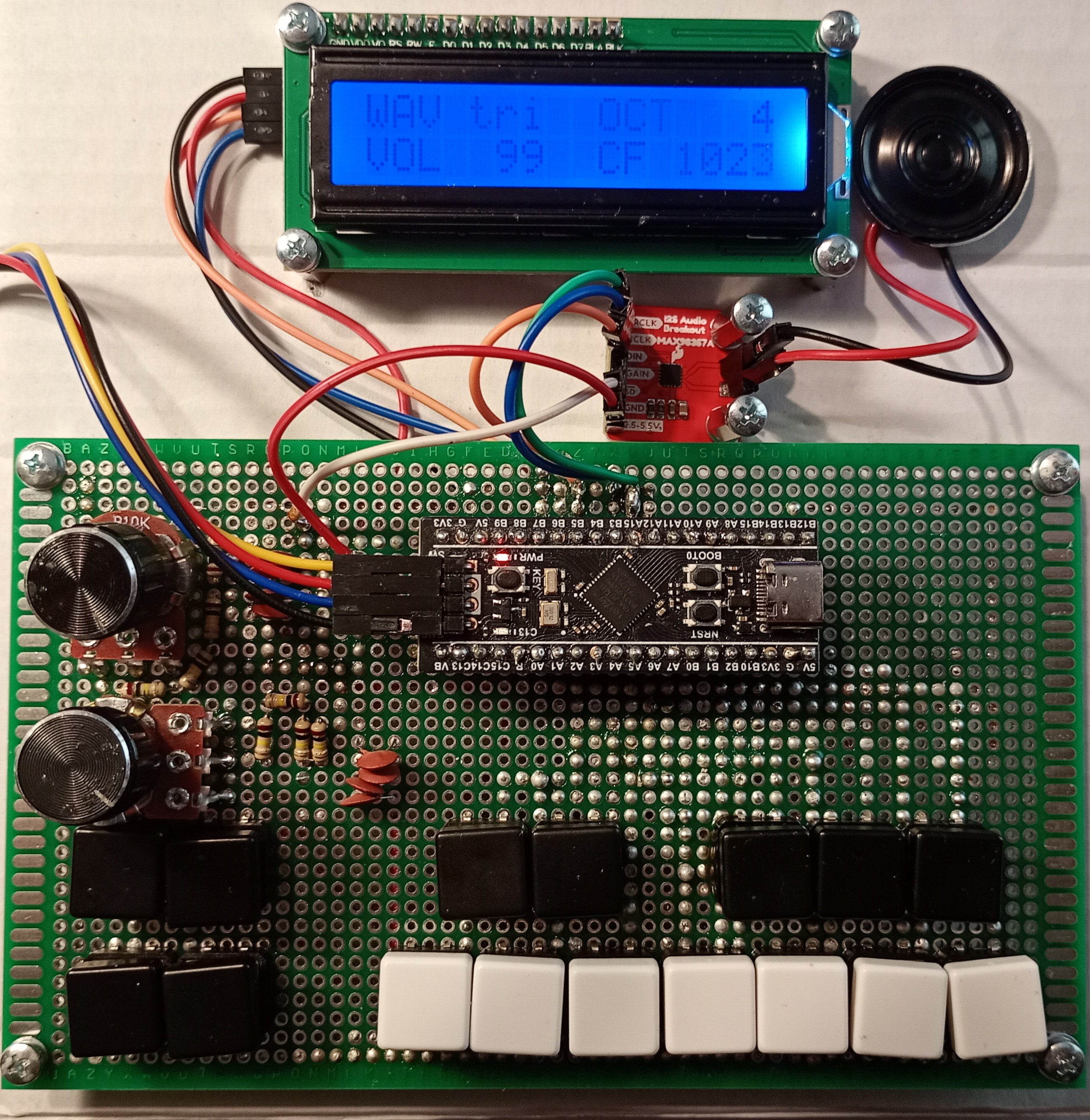
Final device
The following features were implemented:
- synthesis to up to three simultaneous tones
- support for waveforms:
- sine
- triangular
- square
- sawtooth
- 6 octaves of notes, with standard tuning with A4 = 440 Hz pitch
- basic first-order low-pass filter
- LCD display showing current parameter values
The video below is a showcase of different functions. The volume level jumps later in the recording.
Showcase of changing waveforms and octaves
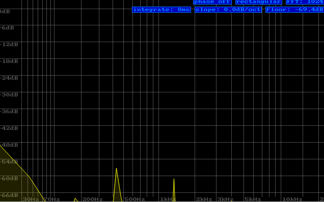
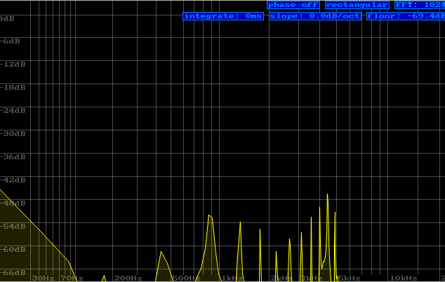
Zoom On The Spectrum Analysis
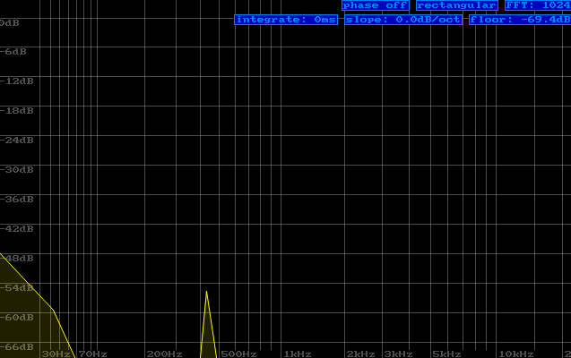
Sine wave at frequency 440 Hz - A4 note
Triangle wave at frequency 440 Hz - A4 note
Sawtooth wave at frequency 440 Hz - A4 note
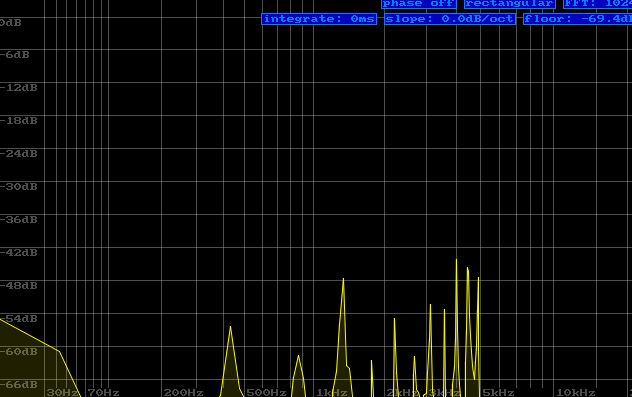
Square wave at frequency 440 Hz - A4 note
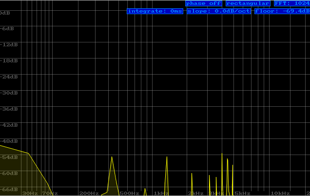
Square wave at frequency 440 Hz - A4 note, with applied low-pass filter with cutoff frequency 302 Hz
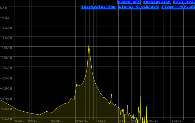
Triangular wave, notes C5 and G5 played simultaneously
How It Works
The algorithm is based on the infinite loop, that either reads from or writes to circular buffer. If there’s a space in the buffer, signal generation will start.
The Buffering
While testing different parameters, I’ve noticed that smaller number of bigger buffers has better performance than using a lot of smaller buffers. Therefore I’ve decided to use one buffer for writing data into, and one for reading data from. When operations on both buffers are complete, they swap roles so new data can be read, and old data to be overwritten. During the buffering, program checks the state of each note-button and then generates signal for each note.
Signal Generation
The signal for an individual note can be generated by using a waveform
function. The waveform function specifies the “shape” of the signal with values
between -1 and 1 over a single period. From the given frequency, the length
of the period can be derived, and after normalizing the provided time value
to the range of one period, the value defined by the “shape” can be returned.
The program iterates over all active keys and applies the waveform function to each note. All output values are summed into the single sample which is then written into the buffer.
To represent the time as the direction I’ve decided to use a global variable
called time_counter which is incremented after every sample, and wraps around
after it reaches the maximum value. Next, the time in seconds is calculated by
dividing time_counter by sampling frequency. With this approach, the passing
of time is strictly correlated with the sound generation, which ensures
continuity of signal and independence of the system clock.
Playback
After the buffer is filled with samples, the data can be sent to the DAC. My implementation uses a non-blocking function to pass samples to the hardware. After the data is transmitted, the interrupt starts execution of another function, which attempts to send new data if it is ready. This chain effect ensures that the program will attempt to send new data with minimal delay. In case data is not ready after the previous transmission finishes, the main loop also tries to execute the send function, as a fallback. To avoid conflicting operations, a simple lock mechanism was implemented.
What Would I Do Differently
This digital synthesizer was my first bigger embedded project. While going back to it I’ve noticed several things I could’ve done differently.
Use Interrupts Instead Of Polling For Keys
In current version, the program has to iterate over all of the keys to check if they are pressed. It would be much more efficient to have an array that would store the key state, which would be altered by interrupts on both key press and release. That should improve performance as access to RAM is generally faster than access to peripherals. That solution would require to either add low pass filters for keys or implement some method of debouncing.
Use DMA With I2S
In current version, data is send via I2C do DAC with non-blocking function that flags interrupt when done. However the transfer of data still is managed by CPU. The DMA approach would free the CPU of this responsibility, so it can focus on other operations.
Use MCU With Double Precision FPU
I’ve noticed that there’s quite noticeable difference of audio quality depending on processing signal with single or double precision floating points. Unfortunately, my MCU has only a single precision FPU and double precision operations are simulated by the software which makes them much slower.